
As part of an undergraduate project at the Singapore University of Technology and Design, students were challenged to design a car powered solely by mechanical energy to transport a 400g payload through an obstacle course. Additional marks were awarded to teams whose cars successfully completed the course.
In charge of CAD, design of mechanism
CAD, Design of final car, Prototyping, Testing
Team of 5
2023
SolidWork, 3D printing
1 semester (14 weeks)
Objective: Design and build a mechanical energy powered toy car that can carry a load travelling across an obstacle course, using the principles of classical mechanics. The rules are as follows:
As a group, we researched and evaluated various mechanical energy sources suitable for the project requirements. The source needed to be compact, lightweight, and capable of storing sufficient energy. We calculated the potential energy each mechanism could store and estimated the theoretical energy required for the car to ascend the starting slope and overcome the obstacles along the course.
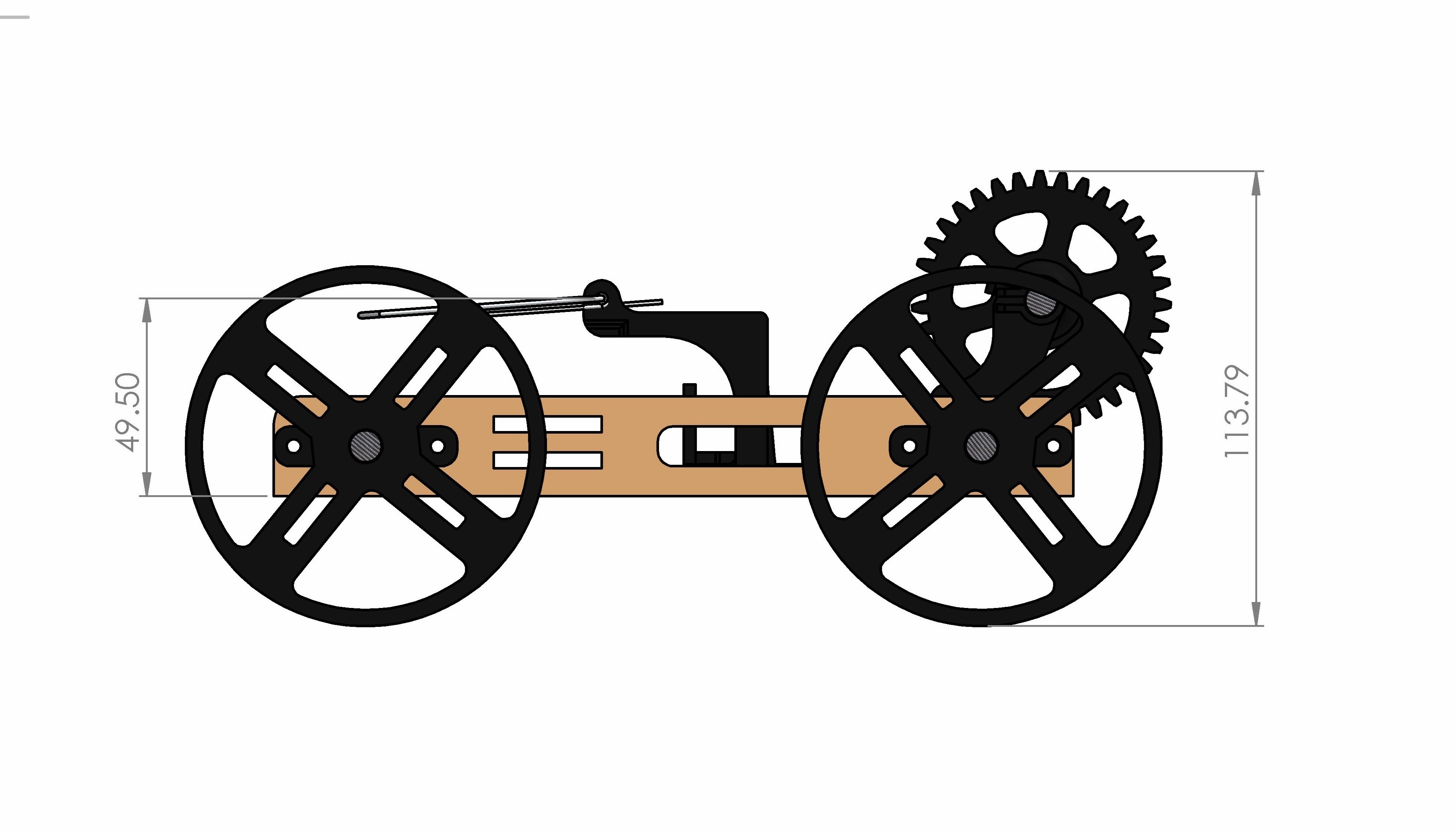
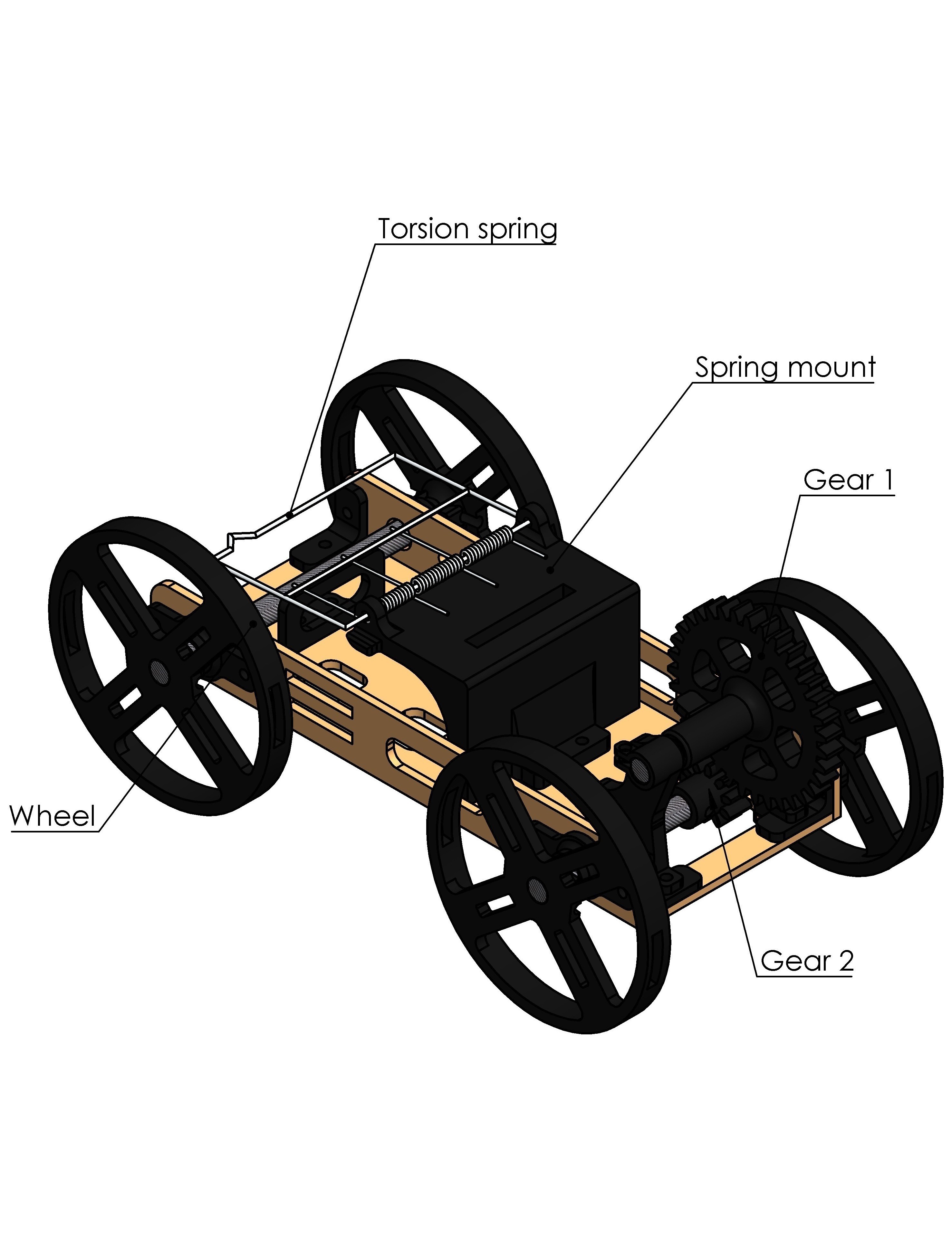
Using torsion spring, we had to maximise the number of wheel turns for every unwound distance of the torsion coil. Hence, we decided to use gears for tranmission of energy from spring to wheel. Using gears meant we had to optimise the gear ratio which refers to: Gear Ratio = (Teeth on Driven Gear) ÷ (Teeth on Driver Gear)
If a small gear turns a large gear, the larger gear will rotate more slowly, but with more torque. The higher the gear ratio, the higher the torque, but speed decreases. For example, if gear ratio is 3:1, the output has 3x more torque than input, but 1/3 speed. We then had to optimise the gear ratio in accordance to the project requirements.
To solve the problems faced, we can use a smaller spring, to allow for easier winding of spring. We can also optimise the design of car to reduce weight. Though we felt the concept had potential, due to the long delivery time of a new spring coil, we decided to switch to a mouse trap torsion spring which we had at hand. We took what we learned from the first prototype and implemented it to the next prototype.
We found that the car moved slowly due to heavy weight. Also, having 3 gears caused there to be alot of friction, causing alot of force from the torsion spring to be ineffieciently transmitted to the rear wheels. Also, the mouse-trap torsion spring did not exert enough force to carry 400g load up a 30 degree slope. Hence, our next step was to 1) make the car lighter, 2) integrate more torsion springs, 3) Reduce number of gears while still maintaining optimal gear ratio.
After a full semester working on the car, it was time to put it to the test........
We found that after a few runs, the torsion spring began to wear on some joints due to the pressure it exerts when wounded up. A future improvement would be to reduce the amount of individual parts to ensure the car is more rigid, allowing for more optimal force transmission from spring to wheels.