Logo
← Other Projects

Omni-Node

Part of a cross‑module project, our team selected the challenge to “Develop a modular, self‑powered IoT sensor for forest monitoring.” Building on that brief, we designed a hybrid power solution—combining a small solar panel with piezoelectric energy harvesting—to keep our sensor running continuously in remote environments.

My Role

Electrical engineer

My Contribution

Concept and Design of Solution, Electronic Circuity, Project Video

About the Team

Team of 8

Year

2025

Platform

ESP32, C++, Fusion360

Time Frame

1 semester (14 weeks)

renders2 Looping animation 1
Looping animation 1 Looping animation 1

Project Video

A 30-second video summarising the project...

Illustrates problem statement and implemented solution
  • Played during project presentaion to professors
  • Created and edited by me :)

Background on forest monitoring IoT sensors

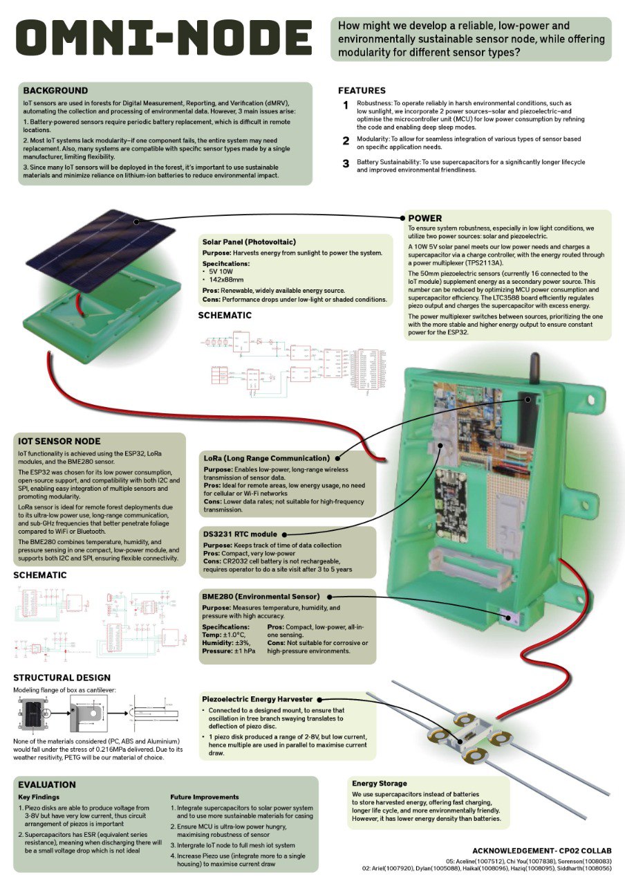
IoT sensors are used in forests for Digital Measurement, Reporting, and Verification (dMRV), automating the collection and processing of environmental data. However, three main issues arise:

  1. Battery-powered sensors require periodic battery replacement, which is difficult in remote locations.
  2. Most IoT systems lack modularity — if one component fails, the entire system may need replacement.
  3. Since many IoT sensors will be deployed in the forest, it is important to use sustainable materials and minimize reliance on lithium-ion batteries to reduce environmental impact.
Problem Statement:

How might we develop a reliable, low-power, and environmentally sustainable sensor node, while offering modularity for different sensor types?

Forest monitoring IoT sensors
  • Some examples of IoT sensors in the market
Slide 2

Our Implemented Design

The main aim for our group was to innovate a solution that adresses the 3 points mentioned above, ensure that the IoT sensor is self-powered, modular and enviromentally sustainable. Our final solution, Omni-Node can be classified into 3 main features:

  1. Robustness: To operate reliably in harsh environmental conditions, such as low sunlight, we incorporate 2 power sources—solar and piezoelectric—and optimise the microcontroller unit (MCU) for low power consumption by refining the code and enabling deep sleep modes.
  2. Modularity: To allow for seamless integration of various types of sensor based on specific application needs.
  3. Battery Sustainability: To use supercapacitors for a significantly longer lifecycle and improved environmental friendliness.
Looping animation 3
Slide 2
Final prototype
  • Uses Solar panels, Piezo discs, ESP32, LoRaWan modules, BME280 Sensor (measures temperature, pressure and humidity)
IoT sensor in operation
  • Powered by Solar Panel and Piezo discs
  • Our presention booth on project showcase day
Looping animation 5 Looping animation 5

How Omni-Node works

The system of Omni-Node operates through four key stages:

  1. Energy Harvesting: Captures ambient power via solar panels and piezoelectric elements.
  2. Energy Storage: Buffers harvested energy in a rechargeable battery or supercapacitor to ensure continuous operation.
  3. IoT Sensing & Data Management: Powers onboard sensors and a wireless module to collect, process, and transmit environmental data.
  4. Enclosure & Form Factor: Integrates all components into a rugged, weather‑resistant housing designed for easy deployment in forest environments.
Slide 2
First drawing drafts of Omni-Node
  • Sketches of sensor case design, circuitry, piezo housing

Energy Harvesting and Storage

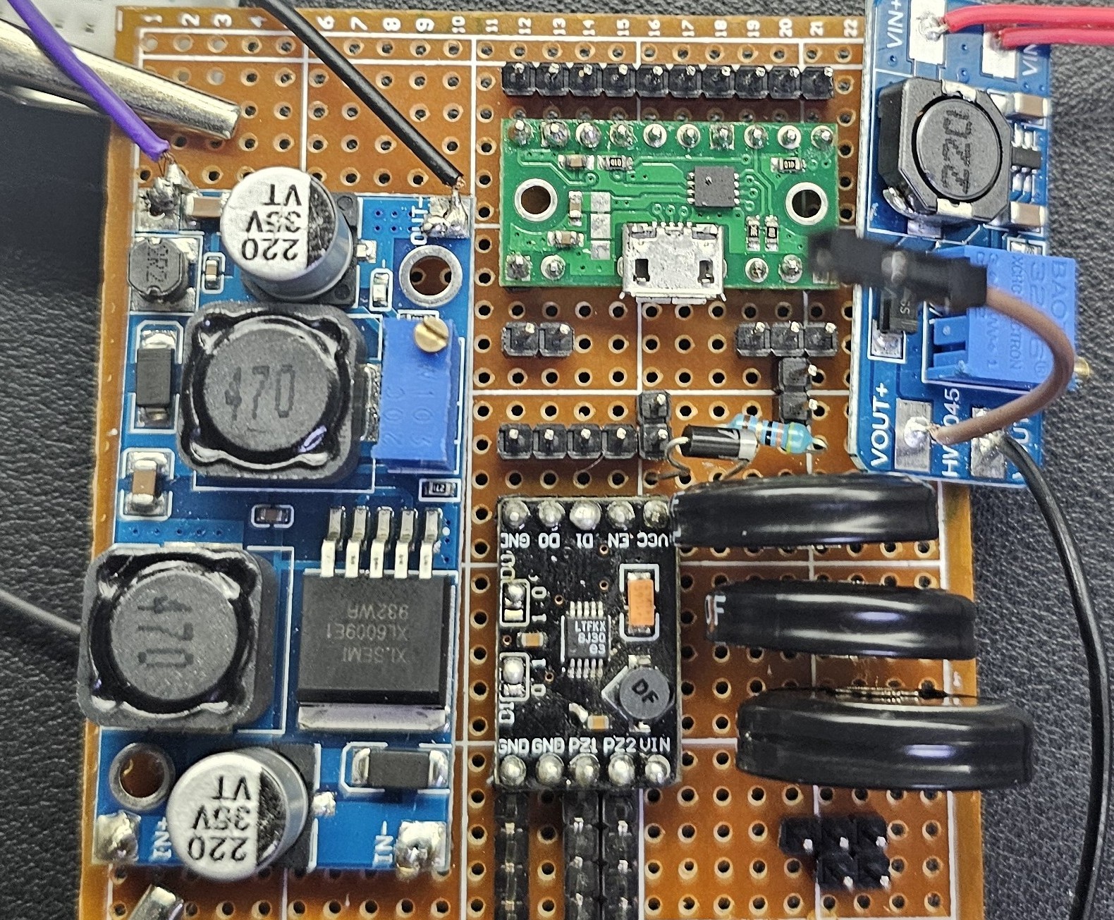
The energy harvesting and storage for Omni-Node is made of 3 main components, the 1) Solar Energy system, the 2) Piezo energy system, and 3) Power Multiplexer.

1) Solar Energy System:

The solar energy system follows the usual Solar Panel, Solar Charge Controller and Battery configuration. The battery which is charged by the solar panel is bucked down (using XL6009 Buck-Boost) then routed to a power multiplexer.

Solar Energy System
  • Made up of Solar Panel, Charge Controller and Battery
Looping animation 5
2) Piezo Energy System:

The energy harvesting system consists of piezoelectric discs, an LTC3588 energy harvesting board, a 1N5817 Schottky diode, a resistor, three 5.5V 1F supercapacitors, and an MT3608 buck converter. The piezo discs are connected in parallel to maximize current output. Their AC signal is routed to the LTC3588 board, which efficiently rectifies the input (AC to DC) and regulates the voltage to 3.3V. This regulated output is used to charge the supercapacitors. Finally, the stored energy from the supercapacitors is stepped down via the MT3608 buck converter and directed to power multiplexer.

Looping animation 5 Looping animation 5
Testing of Piezos
  • First stages of testing how much voltage and current one piezo disc could generate
  • 1 disc generates 3-8v but a low current of 0.1mA.
Piezos Implemented
  • As the tree branch sways or oscillates, the inertia of the attached rod induces deflection in the piezo disc. This mechanical strain produces electrical energy via the piezoelectric effect.
Looping animation 5 Looping animation 5
3) Power Multiplexer

We chose the TPS2113A power multiplexer to manage two input power sources ranging from 2.8V to 5.5V, with built-in reverse current blocking to protect each source. The two inputs are:

  1. The bucked-down output from the solar-powered battery system
  2. The bucked-down output from the supercapacitors in the piezo energy system

The TPS2113A automatically selects the input providing the higher voltage (and thus more power), ensuring that the sensor node is always powered by the most available and stable energy source at any given time.

Circuit diagram
  • Circuit diagram of Power Harvesting and Storage system and soldered circuit
Slide 2
Slide 2
Soldered circuit
  • Soldered circuit, incorporating boost/buck convertors, LTC3588 board, supercapacitors, power multiplexer, diodes, resistors

IoT Sensing & Data Management

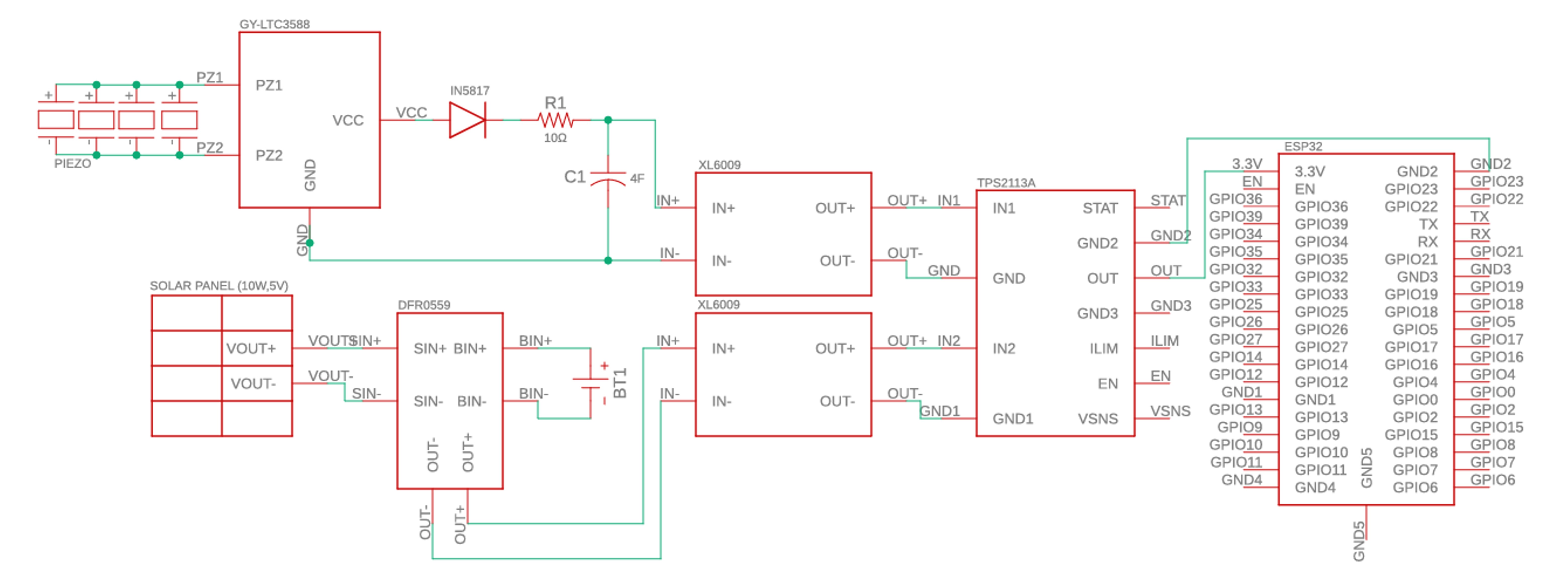
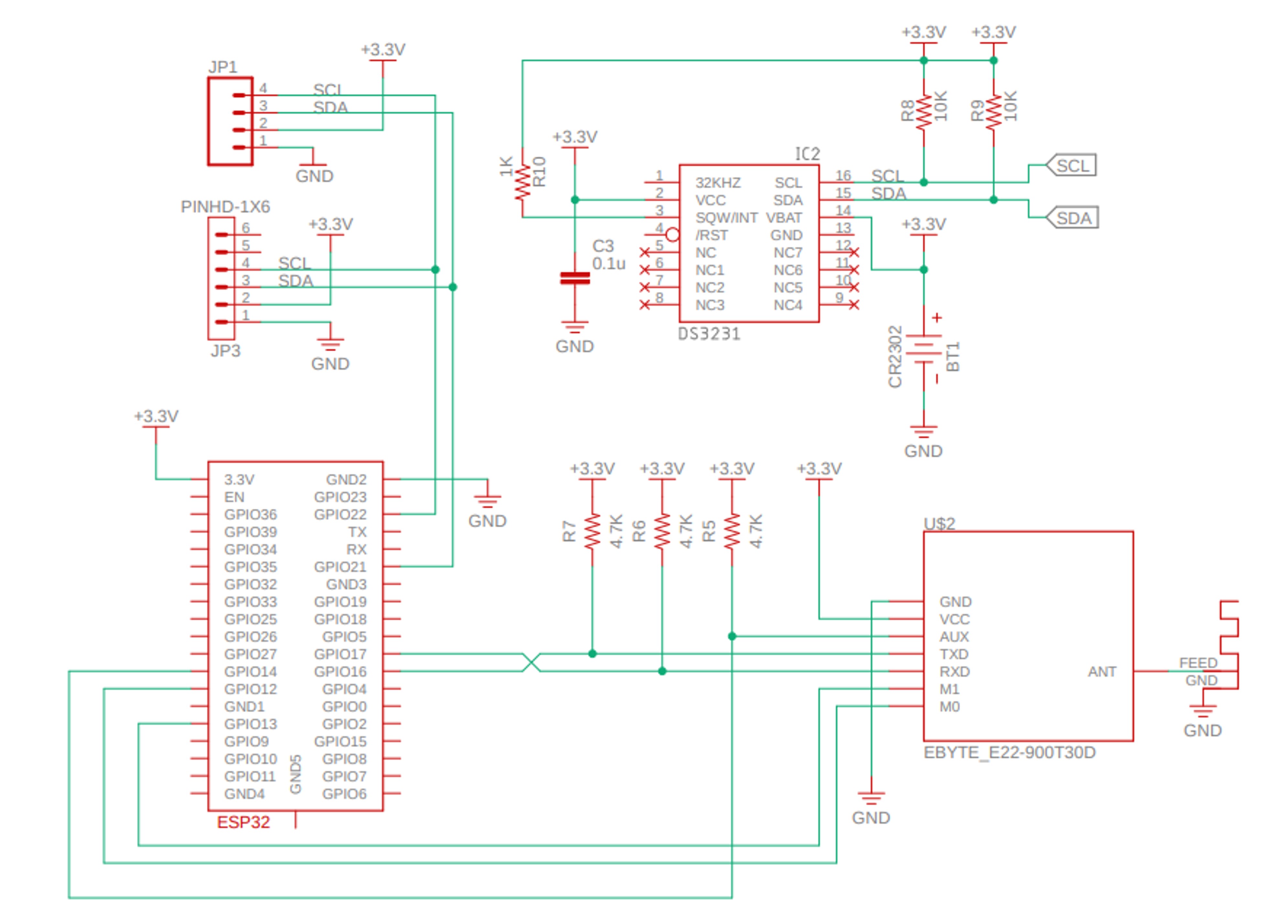
We used ESP32 as the microcontroller, taking in pressure, tempearature and humidity readings from BME280 sensor, and using LoRaWan module to transmit it to another ESP32 LoRaWan pair that acts as a receiver. We chose to use ESP32 as it was relatively low powered and easy to work with since alot of documentation is available online. Though there are much low powered options available but they tend to cost more.

Looping animation 5 Looping animation 5
ESP32 connected to LoRaWan and BME280
  • Shows physical circuitry of ESP32 with components and dashboard for showcasing of sensor readings (credits: to my groupmates Sorenson and Aceline)
Circuit diagram
  • Circuit diagram of ESP32 connected to BME280 and LoRaWan
Slide 2

Enclosure & Form Factor

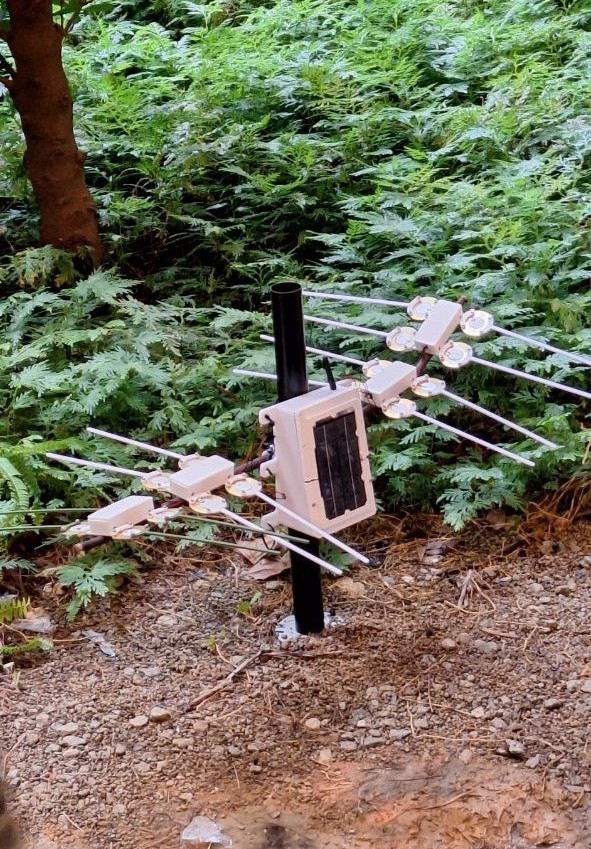
The Omni-Node is designed in two separate components: the piezo housing, which contains only the piezoelectric discs, and the main casing, which holds all other electronic components. During deployment, multiple piezo housings are mounted on the branches of a tree, while the main casing is secured to the trunk.

Our primary focus was to ensure a modular design, allowing each functional component to be replaced independently. As a result, the sensor housing, piezo housings, and solar panel can all be easily swapped or upgraded without affecting the rest of the system.

Looping animation 5 Looping animation 5
The different phases of design
  • Shows CAD models and physical model

Contact Me